# Load soil data from sampling locationsbern_data <- readr::read_csv( here::here("data-raw/soildata/berne_soil_sampling_locations.csv") )# Display datahead(bern_data) |> knitr::kable()
site_id_unique
timeset
x
y
dataset
dclass
waterlog.30
waterlog.50
waterlog.100
ph.0.10
ph.10.30
ph.30.50
ph.50.100
4_26-In-005
d1968_1974_ptf
2571994
1203001
validation
poor
0
0
1
6.071733
6.227780
7.109235
7.214589
4_26-In-006
d1974_1978
2572149
1202965
calibration
poor
0
1
1
6.900000
6.947128
7.203502
7.700000
4_26-In-012
d1974_1978
2572937
1203693
calibration
moderate
0
1
1
6.200000
6.147128
5.603502
5.904355
4_26-In-014
d1974_1978
2573374
1203710
validation
well
0
0
0
6.600000
6.754607
7.200000
7.151129
4_26-In-015
d1968_1974_ptf
2573553
1203935
validation
moderate
0
0
1
6.272715
6.272715
6.718392
7.269008
4_26-In-016
d1968_1974_ptf
2573310
1204328
calibration
poor
0
0
1
6.272715
6.160700
5.559031
5.161655
The dataset on soil samples from Bern holds 13 variables for 1052 entries (more information here):
site_id_unique: The location’s unique site id.
timeset: The sampling year and information on sampling type for soil pH (no label: CaCl\(_2\) laboratory measurement, field: indicator solution used in field, ptf: H\(_2\)O laboratory measurement transferred by pedotransfer function).
x: The x (easting) coordinates in meters following the (CH1903/LV03) system.
y: The y (northing) coordinates in meters following the (CH1903/LV03) system.
dataset: Specification whether a sample is used for model calibration or validation (this is based on randomization to ensure even spatial coverage).
dclass: Soil drainage class
waterlog.30, waterlog.50, waterlog.100: Specification whether soil was water logged at 30, 50, or 100 cm depth (0 = No, 1 = Yes).
ph.0.10, ph.10.30, ph.30.50, ph.50.100: Average soil pH between 0-10, 10-30, 30-50, and 50-100 cm depth.
3.1.1 Covariate data
Now, let’s load all the covariates that we want to produce our soil maps with.
Code
# Get a list with the path to all raster fileslist_raster <- base::list.files( here::here("data-raw/geodata/covariates/"),full.names = T )# Take a random subsetset.seed(3)list_raster_subset <- list_raster |>sample(15)# Display data (lapply to clean names)lapply( list_raster_subset, function(x) sub(".*/(.*)", "\\1", x) ) |>unlist() |>head(5) |>print()
The output above shows the first five raster files with rather cryptic names. The meaning of all 91 raster files are given in Chapter 6. So, make sure to have a look at the list there as it will help you to interpret your model results later on. Let’s look at one of these raster files to get a better feeling for our data. Specifically, let’s look at the slope profile at 2m resolution:
Code
# Load a raster file as example: Picking the slope profile at 2m resolutionraster_example <- terra::rast(list_raster[74])raster_example
class : SpatRaster
dimensions : 986, 2428, 1 (nrow, ncol, nlyr)
resolution : 20, 20 (x, y)
extent : 2568140, 2616700, 1200740, 1220460 (xmin, xmax, ymin, ymax)
coord. ref. : CH1903+ / LV95
source : Se_slope2m.tif
name : Se_slope2m
min value : 0.00000
max value : 85.11286
As shown in the output, a raster object has the following properties (among others, see ?terra::rast):
class: The class of the file, here a SpatRaster.
dimensions: The number of rows, columns, years (if temporal encoding).
resolution: The resolution of the coordinate system, here it is 20 in both axes.
extent: The extent of the coordinate system defined by min and max values on the x and y axes.
coord. ref.: Reference coordinate system. Here, the raster is encoded using the LV95 geodetic reference system from which the projected coordinate system CH1903+ is derived.
source: The name of the source file.
names: The name of the raster file (mostly the file name without file-specific ending)
min value: The lowest value of all cells.
max value: The highest value of all cells.
Tip
The code chunks filtered for a random sub-sample of 15 variables. As described in Chapter 5, your task will be to investigate all covariates and find the ones that can best be used for your modelling task.
4 Mapping the study area
Now, let’s look at a visualisation of this raster file. Since we selected the slope at 2m resolution, we expect a relief-like map with a color gradient that indicates the steepness of the terrain.
Code
# Plot raster exampleterra::plot(raster_example)
Code
# To have some more flexibility, we can plot this in the ggplot-style as such:ggplot2::ggplot() + tidyterra::geom_spatraster(data = raster_example) + ggplot2::scale_fill_viridis_c(na.value =NA,option ="magma",name ="Slope (%) \n" ) + ggplot2::theme_bw() + ggplot2::scale_x_continuous(expand =c(0, 0)) +# avoid gap between plotting area and axis ggplot2::scale_y_continuous(expand =c(0, 0)) + ggplot2::labs(title ="Slope of the Study Area")
Tip
Note that the second plot has different coordinates than the upper one. That is because the data was automatically projected to the World Geodetic System (WGS84, ESPG: 4326).
This looks already interesting but we can put our data into a bit more context. For example, a larger map background would be useful to get a better orientation of our location. Also, it would be nice to see where our sampling locations are and to differentiate these locations by whether they are part of the calibration or validation dataset. Bringing this all together requires some more understanding of plotting maps in R. So, don’t worry if you do not understand everything in the code chunk below and enjoy the visualizations:
Code
# To get our map working correctly, we have to ensure that all the input data# is in the same coordinate system. Since our Bern data is in the Swiss # coordinate system, we have to transform the sampling locations to the # World Geodetic System first.# To look up EPSG Codes: https://epsg.io/# World Geodetic System 1984: 4326# Swiss CH1903+ / LV95: 2056# For the raster:r <- terra::project(raster_example, "+init=EPSG:4326")# Let's make a function for transforming the sampling locations:change_coords <-function(data, from_CRS, to_CRS) {# Check if data input is correctif (!all(names(data) %in%c("id", "lat", "lon"))) {stop("Input data needs variables: id, lat, lon") }# Create simple feature for old CRS sf_old_crs <- sf::st_as_sf(data, coords =c("lon", "lat"), crs = from_CRS)# Transform to new CRS sf_new_crs <- sf::st_transform(sf_old_crs, crs = to_CRS) sf_new_crs$lat <- sf::st_coordinates(sf_new_crs)[, "Y"] sf_new_crs$lon <- sf::st_coordinates(sf_new_crs)[, "X"] sf_new_crs <- sf_new_crs |> dplyr::as_tibble() |> dplyr::select(id, lat, lon)# Return new CRSreturn(sf_new_crs)}# Transform dataframescoord_cal <- bern_data |> dplyr::filter(dataset =="calibration") |> dplyr::select(site_id_unique, x, y) |> dplyr::rename(id = site_id_unique, lon = x, lat = y) |>change_coords(from_CRS =2056, to_CRS =4326 )coord_val <- bern_data |> dplyr::filter(dataset =="validation") |> dplyr::select(site_id_unique, x, y) |> dplyr::rename(id = site_id_unique, lon = x, lat = y) |>change_coords(from_CRS =2056, to_CRS =4326 )
Code
# Notes: # - This code may only work when installing the development branch of {leaflet}:# remotes::install_github('rstudio/leaflet')# - You might have to do library(terra) for R to find functions needed in the backendlibrary(terra)# Let's get a nice color palette now for easy referencepal <- leaflet::colorNumeric("magma", terra::values(r),na.color ="transparent" )# Next, we build a leaflet mapleaflet::leaflet() |># As base maps, use two provided by ESRI leaflet::addProviderTiles(leaflet::providers$Esri.WorldImagery, group ="World Imagery") |> leaflet::addProviderTiles(leaflet::providers$Esri.WorldTopoMap, group ="World Topo") |># Add our raster file leaflet::addRasterImage( r,colors = pal,opacity =0.6,group ="raster" ) |># Add markers for sampling locations leaflet::addCircleMarkers(data = coord_cal,lng =~lon, # Column name for x coordinateslat =~lat, # Column name for y coordinatesgroup ="training",color ="black" ) |> leaflet::addCircleMarkers(data = coord_val,lng =~lon, # Column name for x coordinateslat =~lat, # Column name for y coordinatesgroup ="validation",color ="red" ) |># Add some layout and legend leaflet::addLayersControl(baseGroups =c("World Imagery","World Topo"),position ="topleft",options = leaflet::layersControlOptions(collapsed =FALSE),overlayGroups =c("raster", "training", "validation") ) |> leaflet::addLegend(pal = pal,values = terra::values(r),title ="Slope (%)")
Note
This plotting example is based to the one shown in the AGDS 2 tutorial “Handful of Pixels” on phenology. More information on using spatial data in R can be found there in the Chapter on Geospatial data in R.
That looks great! At first glance, it is a bit crowded but once you scroll in you can investigate our study area quite nicely. You can check whether the slope raster file makes sense by comparing it against the base maps. Can you see how cliffs along the Aare river, hills, and even gravel quarries show high slopes? We also see that our validation dataset is nicely distributed across the area covered by the training dataset.
Now that we have played with a few visualizations, let’s get back to preparing our data. The {terra} package comes with the very useful tool to stack multiple raster on top of each other, if they are of the same spatial format. To do so, we just have to feed in the vector of file names list_raster_subset:
Code
# Load all files as one batchall_rasters <- terra::rast(list_raster_subset)all_rasters
Now, we do not want to have the covariates’ data from all cells in the raster file. Rather, we want to reduce our stacked rasters to the x and y coordinates for which we have soil sampling data. We can do this using the terra::extract() function. Then, we want to merge the two dataframes of soil data and covariates data by their coordinates. Since the order of the covariate data is the same as the Bern data, we can simply bind their columns with cbind():
Code
# Extract coordinates from sampling locationssampling_xy <- bern_data |> dplyr::select(x, y)# From all rasters, extract values for sampling coordinatescovar_data <- terra::extract(all_rasters, # The raster we want to extract from sampling_xy, # A matrix of x and y values to extract forID =FALSE# To not add a default ID column to the output )final_data <-cbind(bern_data, covar_data)head(final_data) |> knitr::kable()
site_id_unique
timeset
x
y
dataset
dclass
waterlog.30
waterlog.50
waterlog.100
ph.0.10
ph.10.30
ph.30.50
ph.50.100
geo500h1id
Se_n_aspect2m
mt_rr_y
Se_curvplan2m_std_5c
vdcn25
lsf
Se_conv2m
Se_slope2m
Se_MRVBF2m
Se_curvprof2m_fmean_50c
Se_diss2m_50c
Se_vrm2m
Se_curvplan2m
Se_SAR2m
Se_curv6m
4_26-In-005
d1968_1974_ptf
2571994
1203001
validation
poor
0
0
1
6.071733
6.227780
7.109235
7.214589
6
-0.2402939
9931.120
0.6229440
65.62196
0.0770846
-40.5395088
1.1250136
6.950892
-0.0382753
0.3934371
0.0002450
-1.0857303
4.000910
-0.5886537
4_26-In-006
d1974_1978
2572149
1202965
calibration
poor
0
1
1
6.900000
6.947128
7.203502
7.700000
6
0.4917848
9931.672
2.2502327
69.16074
0.0860347
19.0945148
1.3587183
6.984581
-0.0522900
0.4014700
0.0005389
-0.3522736
4.001326
0.1278165
4_26-In-012
d1974_1978
2572937
1203693
calibration
moderate
0
1
1
6.200000
6.147128
5.603502
5.904355
6
-0.9633239
9935.438
0.2292406
63.57096
0.0737963
-9.1396294
0.7160403
6.990917
-0.0089129
0.6717541
0.0000124
-0.2168447
4.000320
-0.0183221
4_26-In-014
d1974_1978
2573374
1203710
validation
well
0
0
0
6.600000
6.754607
7.200000
7.151129
6
-0.4677161
9939.923
0.1029889
64.60535
0.0859686
-0.9318936
0.8482135
6.964162
-0.0331309
0.4988544
0.0000857
-0.0272214
4.000438
-0.0706228
4_26-In-015
d1968_1974_ptf
2573553
1203935
validation
moderate
0
0
1
6.272715
6.272715
6.718392
7.269008
6
0.5919228
9942.032
0.9816071
61.16533
0.0650000
4.2692256
1.2301254
6.945287
-0.0202268
0.6999696
0.0002062
0.2968794
4.000948
0.0476020
4_26-In-016
d1968_1974_ptf
2573310
1204328
calibration
poor
0
0
1
6.272715
6.160700
5.559031
5.161655
6
0.5820994
9940.597
0.3455668
55.78354
0.0731646
-0.1732794
1.0906221
6.990967
-0.0014042
0.3157751
0.0001151
0.0100844
4.000725
0.0400775
Great that worked without problems!
Now, not all our covariates may be continuous variables and therefore have to be encoded as factors. As an easy check, we can take the original corvariates data and check for the number of unique values in each raster. If the variable is continuous, we expect that there are a lot of different values - at maximum 1052 different values because we have that many entries. So, let’s have a look and assume that variables with 10 or less different values are categorical variables.
Code
cat_vars <- covar_data |># Get number of distinct values per variable dplyr::summarise(dplyr::across(dplyr::everything(), ~ dplyr::n_distinct(.))) |># Turn df into long format for easy filtering tidyr::pivot_longer(dplyr::everything(), names_to ="variable", values_to ="n") |># Filter out variables with 10 or less distinct values dplyr::filter(n <=10) |># Extract the names of these variables dplyr::pull('variable')cat("Variables with less than 10 distinct values:", ifelse(length(cat_vars) ==0, "none", cat_vars))
Variables with less than 10 distinct values: geo500h1id
Now that we have the names of the categorical values, we can mutate these columns in our df using the base function as.factor():
We are almost done with our data preparation, we just need to reduce it to sampling locations for which we have a decent amount of data on the covariates. Else, we blow up the model calibration with data that is not informative enough.
Code
# Get number of rows to calculate percentagesn_rows <-nrow(final_data)# Get number of distinct values per variablefinal_data |> dplyr::summarise(dplyr::across(dplyr::everything(), ~length(.) -sum(is.na(.)))) |> tidyr::pivot_longer(dplyr::everything(), names_to ="variable", values_to ="n") |> dplyr::mutate(perc_available =round(n / n_rows *100)) |> dplyr::arrange(perc_available) |>head(10) |> knitr::kable()
variable
n
perc_available
ph.30.50
856
81
ph.10.30
866
82
ph.50.100
859
82
timeset
871
83
ph.0.10
870
83
dclass
1006
96
site_id_unique
1052
100
x
1052
100
y
1052
100
dataset
1052
100
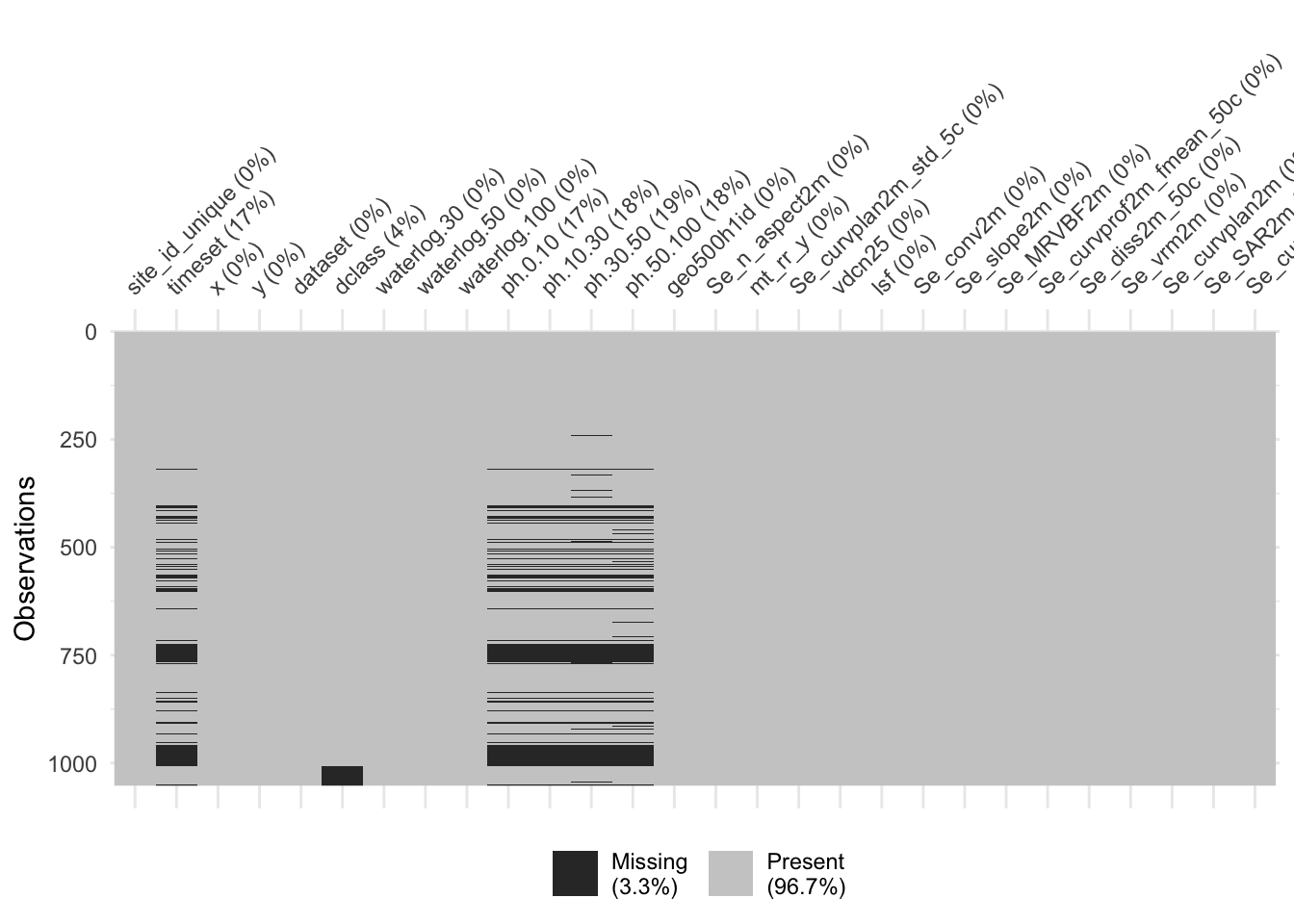
This looks good, we have no variable with a substantial amount of missing data. Generally, only pH measurements are lacking, which we should keep in mind when making predictions and inferences. Another great way to explore your data, is using the {visdat} package:
Code
final_data |> visdat::vis_miss()
Alright, we see that we are not missing any data in the covariate data. Mostly sampled data, specifically pH and timeset data is missing. We also see that this missing data is mostly from the same entry, so if we keep only entries where we have pH data - which is what we are interested here - we have a dataset with pracitally no missing data.